Engine Management System
Modern ECU's
Modern E.C.U.s use a microprocessor which can process the inputs from the engine sensors in real-time. An Electronic Control Unit contains the hardware and software (firmware). The hardware consists of electronic components on a printed circuit board (P.C.B.), ceramic substrate or a thin laminate substrate. The main component on this circuit board is a micro controller chip (CPU). The software is stored in the microcontroller or other chips on the P.C.B., typically in E.P.R.O.Ms or flash memory so the C.P.U. can be re-programmed by uploading updated code or replacing chips. This is also referred to as an (electronic) Engine Management System (E.M.S.). Sophisticated engine management systems receive inputs from other sources, and control other parts of the engine; for instance, some variable valve timing systems are electronically controlled, and turbocharger waste gates can also be managed. They also may communicate with transmission control units or directly interface electronically controlled automatic transmissions, traction control systems, and the like. The Controller Area Network or CAN bus automotive network is often used to achieve communication between these devices. Modern E.C.U.s sometimes include features such as cruise control, transmission control, anti-skid brake control, and anti-theft control, etc.
An engine control unit (ECU) is a type of electronic control unit that controls a series of actuators on an internal combustion engine to ensure optimal engine performance. It does this by reading values from a multitude of sensors in the engine compartment, interpreting the data, and adjusting the engine actuators accordingly.
Before ECUs, air-fuel mixture, ignition timing, and idle speed were mechanically set and dynamically controlled by mechanical and pneumatic means.
A modern ECU might contain a 32-bit, 40-MHz processor. This may not sound fast compared to the 500- to 1,000-MHz processor you probably have in your PC, but remember that the processor in your car is running much more efficient code than the one in your PC. The code in an average ECU takes up less than 1 megabyte (MB) of memory. By comparison, you probably have at least 2 gigabytes (GB) of programs on your computer -- that's 2,000 times the amount in an ECU.
Need of ECU's
Before emissions laws were enacted, it was possible to build a car engine without ECU. With the enactment of increasingly stricter emissions laws, sophisticated control schemes were needed to regulate the air/fuel mixture so that the catalytic converter could remove a lot of the pollution from the exhaust.
Controlling the engine is the most processor-intensive job in a car, and the engine control unit (ECU) is the most powerful computer on most cars. The ECU uses closed-loop control, a control scheme that monitors outputs of a system to control the inputs to a system, managing the emissions and fuel economy of the engine as well as a host of other parameters. Gathering data from dozens of different sensors, the ECU knows everything from the coolant temperature to the amount of oxygen in the exhaust. With this data, it performs millions of calculations each second, including looking up values in tables, calculating the results of long equations to decide on the best spark timing and determining how long the fuel injector is open. The ECU does all of this to ensure the lowest emissions and best mileage.
Some of the important reasons for ECU:
Working of ECU
Control of air/fuel ratio
Most modern engines use some type of fuel injection to deliver fuel to the cylinders. The ECU determines the amount of fuel to inject based on a number of sensor readings. Oxygen sensors tell the ECU whether the engine is running rich (too much fuel/too little oxygen) or running lean (too much oxygen/too little fuel) as compared to ideal conditions (known as stoichiometric).
The throttle position sensors tell the ECU how far the throttle plate is opened when you press the accelerator.
The mass air flow sensor measures the amount of air flowing into the engine through the throttle plate.
The engine coolant temperature sensor measures whether the engine is warmed up or cool. (If the engine is still cool, additional fuel will be injected.)
Air/fuel mixture control of carburetors with computers is designed with a similar principle, but a mixture control solenoid or stopper motor is incorporated in the float bowl of the carburetor.
Control of ignition timing
A spark ignition engine requires a spark to initiate combustion in the combustion chamber. An ECU can adjust the exact timing of the spark (called ignition timing) to provide better power and economy. If the ECU detects knock, a condition which is potentially destructive to engines, and determines it to be the result of the ignition timing occurring too early in the compression stroke, it will delay (retard) the timing of the spark to prevent this. Since knock tends to occur more easily at lower rpm, the ECU may send a signal for the automatic transmission to downshift as a first attempt to alleviate knock.
Control of idle speed
Most engine systems have idle speed control built into the ECU. The engine RPM is monitored by the crankshaft position sensor which plays a primary role in the engine timing functions for fuel injection, spark events, and valve timing. Idle speed is controlled by a programmable throttle stop or an idle air bypass control stepper motor. Early carburetor-based systems used a programmable throttle stop using a bidirectional DC motor. Early Throttle body injection (TBI) systems used an idle air control stepper motor. Effective idle speed control must anticipate the engine load at idle. A full authority throttle control system may be used to control idle speed, provide cruise control functions and top speed limitation.
Control of variable valve timing
Some engines have Variable Valve Timing. In such an engine, the ECU controls the time in the engine cycle at which the valves open. The valves are usually opened sooner at higher speed than at lower speed. This can optimize the flow of air into the cylinder, increasing power and fuel economy.
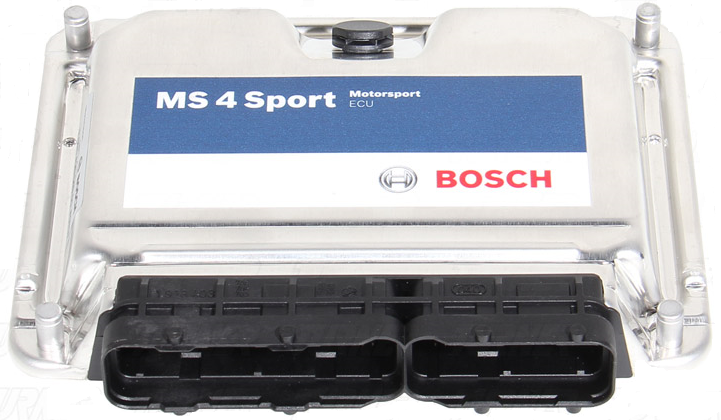
ECU Components
The processor is packaged in a module with hundreds of other components on a multi-layer circuit board. Some of the other components in the ECU that support the processor are:,
Analog-to-digital converters - These devices read the outputs of some of the sensors in the car, such as the oxygen sensor. The output of an oxygen sensor is an analog voltage, usually between 0 and 1.1 volts (V). The processor only understands digital numbers, so the analog-to-digital converter changes this voltage into a 10-bit digital number.
High-level digital outputs - On many modern cars, the ECU fires the spark plugs, opens and closes the fuel injectors and turns the cooling fan on and off. All of these tasks require digital outputs. A digital output is either on or off -- there is no in-between. For instance, an output for controlling the cooling fan might provide 12 V and 0.5 amps to the fan relay when it is on, and 0 V when it is off. The digital output itself is like a relay. The tiny amount of power that the processor can output energizes the transistor in the digital output, allowing it to supply a much larger amount of power to the cooling fan relay, which in turn provides a still larger amount of power to the cooling fan.
Digital-to-analog converters - Sometimes the ECU has to provide an analog voltage output to drive some engine components. Since the processor on the ECU is a digital device, it needs a component that can convert the digital number into an analog voltage.
Signal conditioners - Sometimes the inputs or outputs need to be adjusted before they are read. For instance, the analog-to-digital converter that reads the voltage from the oxygen sensor might be set up to read a 0- to 5-V signal, but the oxygen sensor outputs a 0- to 1.1-V signal. A signal conditioner is a circuit that adjusts the level of the signals coming in or out. For instance, if we applied a signal conditioner that multiplied the voltage coming from the oxygen sensor by 4, we'd get a 0- to 4.4-V signal, which would allow the analog-to-digital converter to read the voltage more accurately.
Communication chips These chips implement the various communications standards that are used on cars. There are several standards used, but the one that is starting to dominate in-car communications is called CAN (controller-area networking). This communication standard allows for communication speeds of up to 500 kilobits per second (Kbps). That's a lot faster than older standards. This speed is becoming necessary because some modules communicate data onto the bus hundreds of times per second. The CAN bus communicates using two wires.
Another benefit of having a communications bus is that each module can communicate faults to a central module, which stores the faults and can communicate them to an off-board diagnostic tool. This can make it easier for technicians to diagnose problems with the car, especially intermittent problems, which are notorious for disappearing as soon as you bring the car in for repairs.
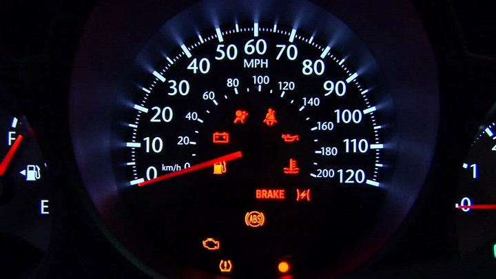
The instrument cluster gathers and displays data from various parts of the vehicle. Most of this data is already used by other modules in the car. For instance, the ECU knows the coolant temperature and engine speed. The transmission controller knows the vehicle speed. The controller for the anti-lock braking system (ABS) knows if there is a problem with the ABS.
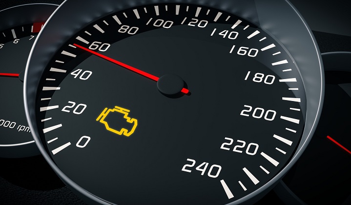
On-Board Diagnostics OBD
On-board diagnostics (OBD)is an automotive term referring to a vehicle's self-diagnostic and reporting capability. OBD systems give the vehicle owner or repair technician access to the status of the various vehicle subsystems. The amount of diagnostic information available via OBD has varied widely since its introduction in the early 1980s versions of on-board vehicle computers. Early versions of OBD would simply illuminate a malfunction indicator light or "idiot light" if a problem was detected but would not provide any information as to the nature of the problem. Modern OBD implementations use a standardized digital communications port to provide real-time data in addition to a standardized series of diagnostic trouble codes, or DTCs, which allow one to rapidly identify and remedy malfunctions within the vehicle.
OBD-I
The regulatory intent of OBD-I, was to encourage auto manufacturers to design reliable emission control systems that remain effective for the vehicle's "useful life".[citation needed] The Diagnostic Trouble Codes (DTCs) of OBD-I vehicles can usually be found without an expensive 'scan tool'. Each manufacturer used their own diagnostic link connector (DLC), DLC location, DTC definitions, and procedure to read the DTCs from the vehicle. DTCs from OBD-I cars are often read through the blinking patterns of the 'Check Engine Light' (CEL) or 'Service Engine Soon' (SES) light. By connecting certain pins of the diagnostic connector, the 'Check Engine' light will blink out a two-digit number that corresponds to a specific error condition.
The DTCs of some OBD-I cars are interpreted in different ways, however. Cadillac (gasoline) fuel-injected vehicles are equipped with actual on-board diagnostics, providing trouble codes, actuator tests and sensor data through the new digital Electronic Climate Control display.
Holding down 'Off' and 'Warmer' for several seconds activates the diagnostic mode without the need for an external scan tool. Some Honda engine computers are equipped with LEDs that light up in a specific pattern to indicate the DTC. General Motors, some 1989-1995 Ford vehicles (DCL), and some 1989-1995 Toyota/Lexus vehicles have a live sensor data stream available, however, many other OBD-I equipped vehicles do not. OBD-I vehicles have fewer DTCs available than for OBD-II equipped vehicles.
OBD-II
OBD-II is an improvement over OBD-I in both capability and standardization. The OBD-II standard specifies the type of diagnostic connector and its pinout, the electrical signalling protocols available, and the messaging format. It also provides a candidate list of vehicle parameters to monitor along with how to encode the data for each. There is a pin in the connector that provides power for the scan tool from the vehicle battery, which eliminates the need to connect a scan tool to a power source separately. However, some technicians might still connect the scan tool to an auxiliary power source to protect data in the unusual event that a vehicle experiences a loss of electrical power due to a malfunction. Finally, the OBD-II standard provides an extensible list of DTCs. As a result of this standardization, a single device can query the on-board computer(s) in any vehicle. This OBD-II came in two models OBD-IIA and OBD-IIB. OBD-II standardization was prompted by emissions requirements, and though only emission-related codes and data are required to be transmitted through it, most manufacturers have made the OBD-II Data Link Connector the only one in the vehicle through which all systems are diagnosed and programmed. OBD-II Diagnostic Trouble Codes are 4-digit, preceded by a letter: P for engine and transmission (powertrain), B for body, C for chassis, and U for network.